
ICS Light Cubes
A modular, reconfigurable lighting ecosystem designed for adaptive environments.
1. Concept & Ideation
The Limitations of Static Lighting Residential lighting forces a binary choice: high-intensity overhead lighting (stimulation) or fixed ambient lamps (cord-restricted). There was no solution for “migratory” lighting that moves with the user without the friction of cables.
- Objective: Create a tangible, battery-free lighting object that transitions from a single task light to a linear array in seconds.
- Philosophy: “Tangible Interaction.” Eliminating switches in favor of physical docking as the trigger for illumination.
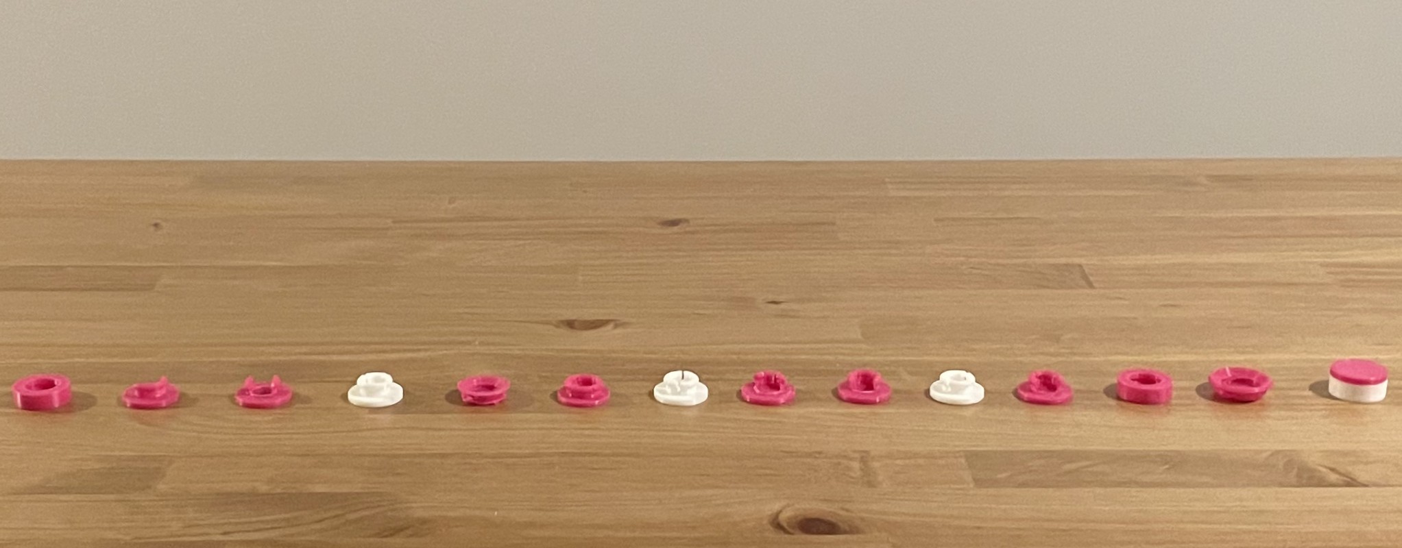
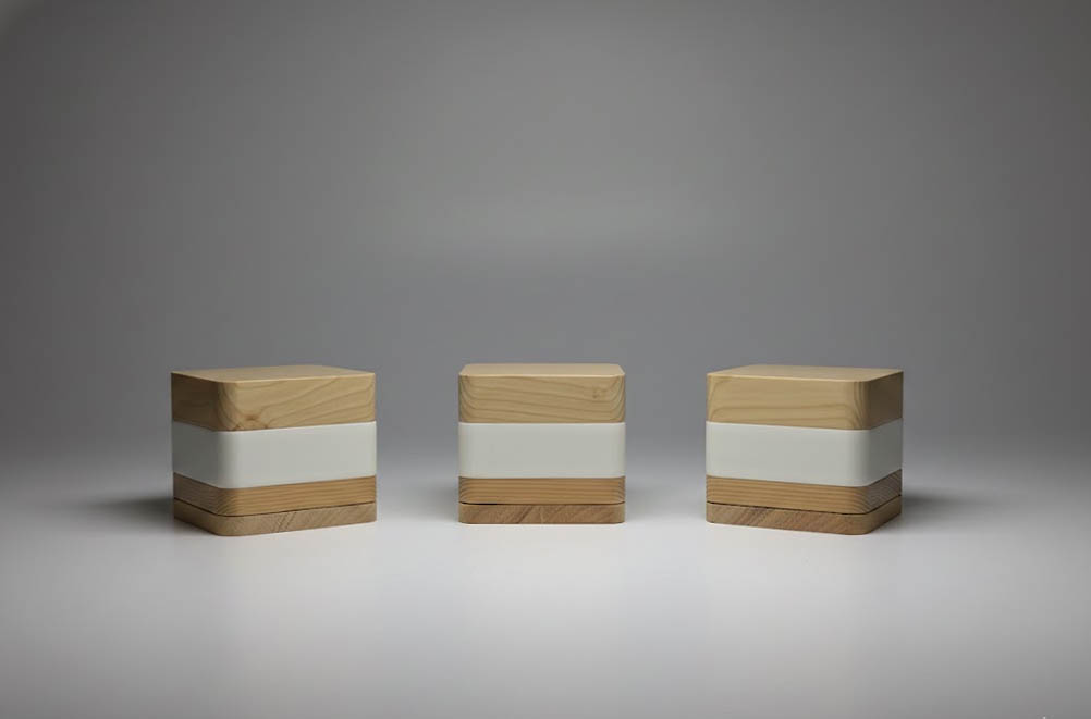
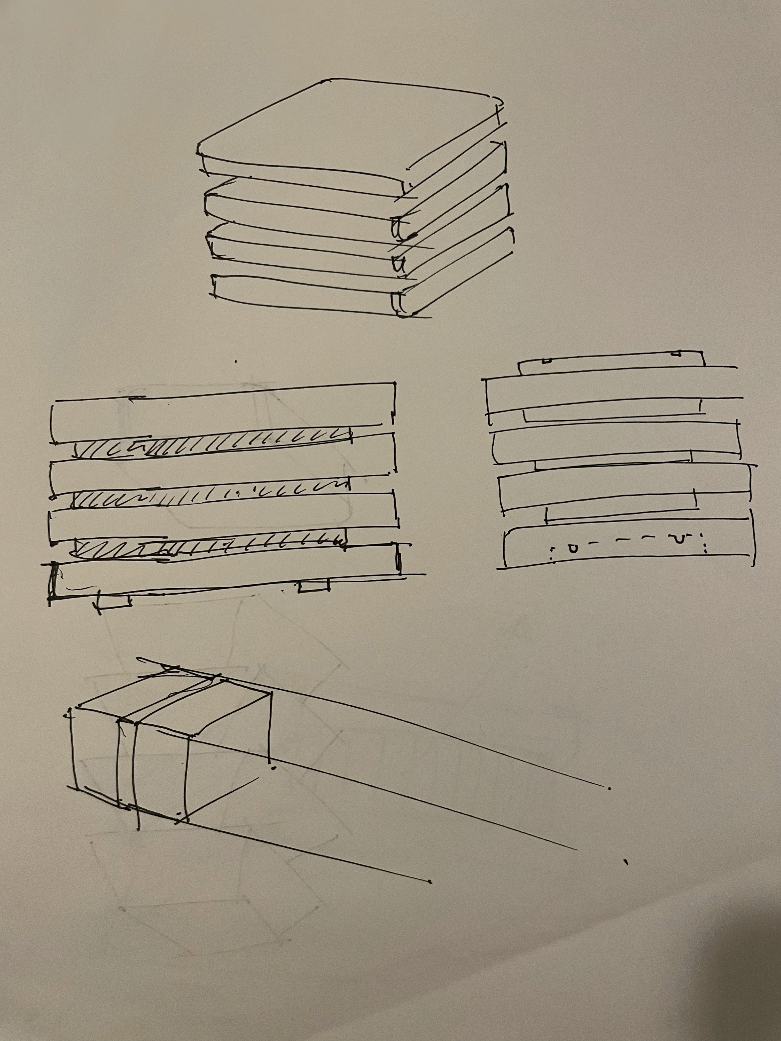 Initial exploration of form and modularity.
2. Prototyping
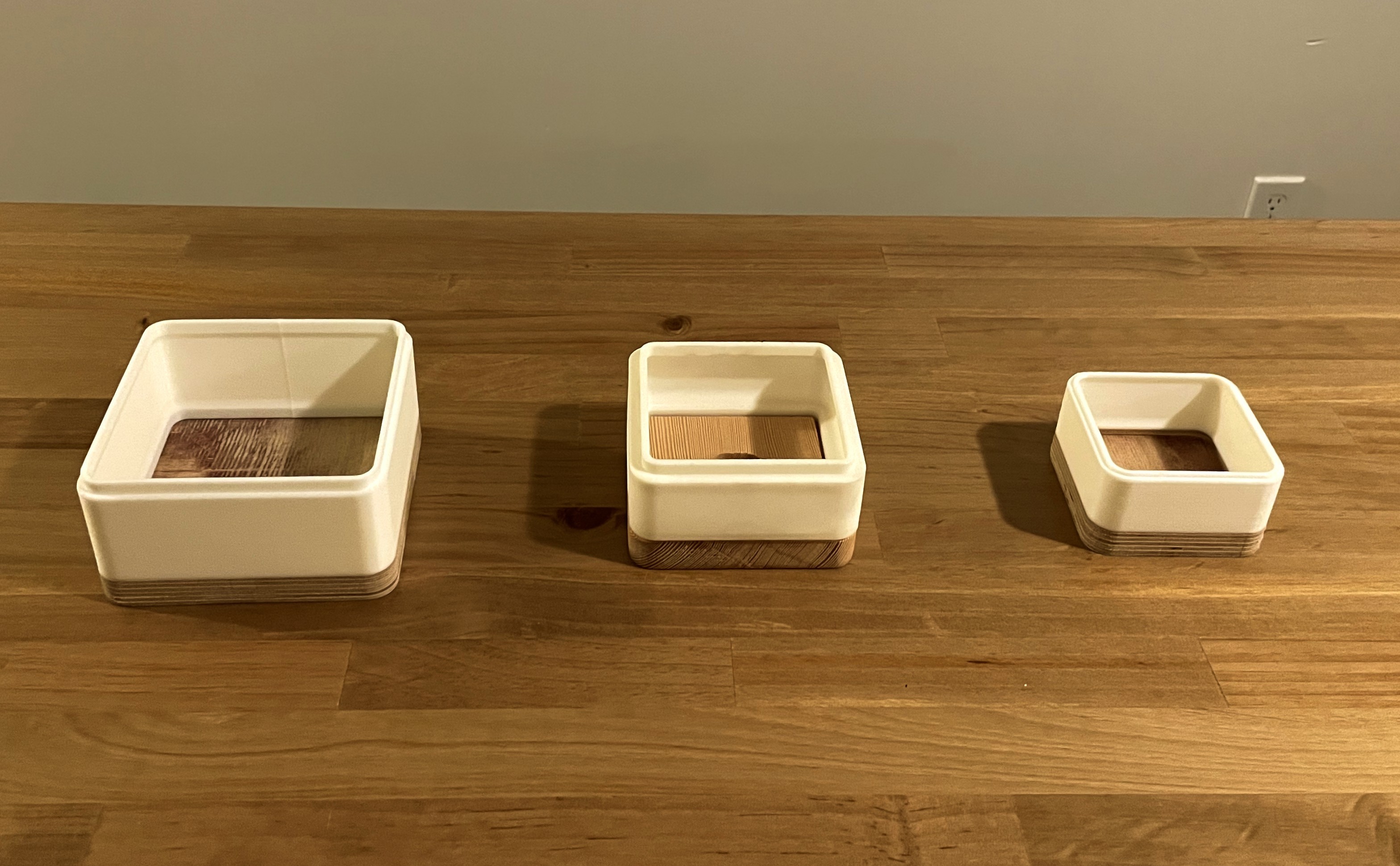
Defining the scale was critical. The object had to feel substantial enough to be furniture, but light enough to be portable.
3. System Architecture
Contact-Based Power Topology
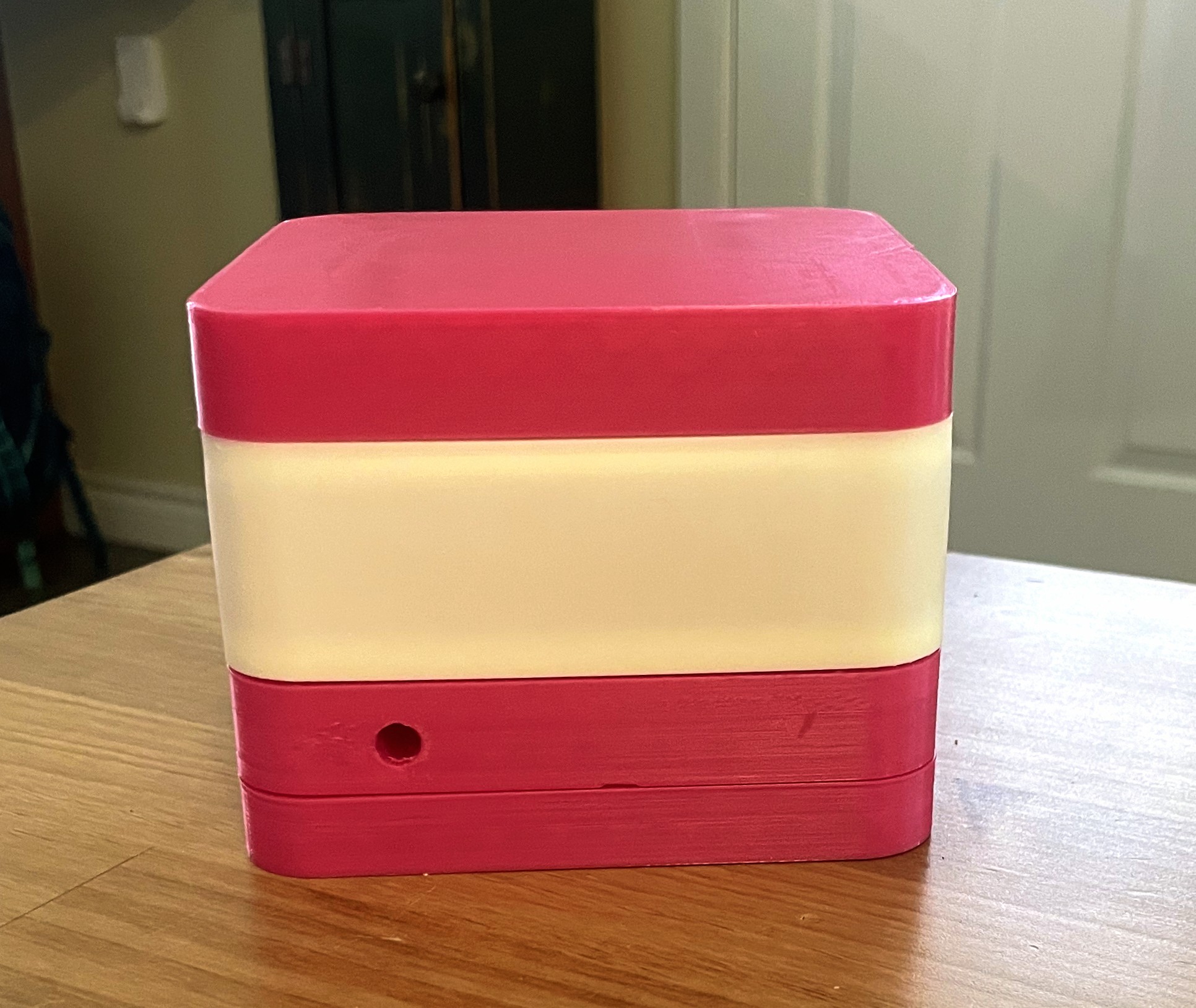
To eliminate cables while maintaining safety, I engineered a contact-based power architecture using the USB-A Standard (5V).
 5V Power topology and interconnects.
- SELV Compliance: By utilizing 5V DC, the system remains within Safety Extra Low Voltage limits, making the exposed contact pads on the base station “human-safe” to touch.
- Magnetic Assist: Embedded Neodymium magnets provide a “self-aligning” force, pulling the cube into the correct docking position to guarantee pin-to-pad alignment without user effort.
4. Mechanical Design
The Serviceability Mandate
A core requirement was that the device must be repairable. I refused to use permanent adhesives to seal the electronics inside the wood.
The “Fastmount” Inspiration I researched architectural panel mounting systems and adapted the geometry of the industrial Fastmount friction-clip system for 3D printing. The final design allows the internal electronics core to “snap” into the wooden shell.
 Detail of the friction-clip system.
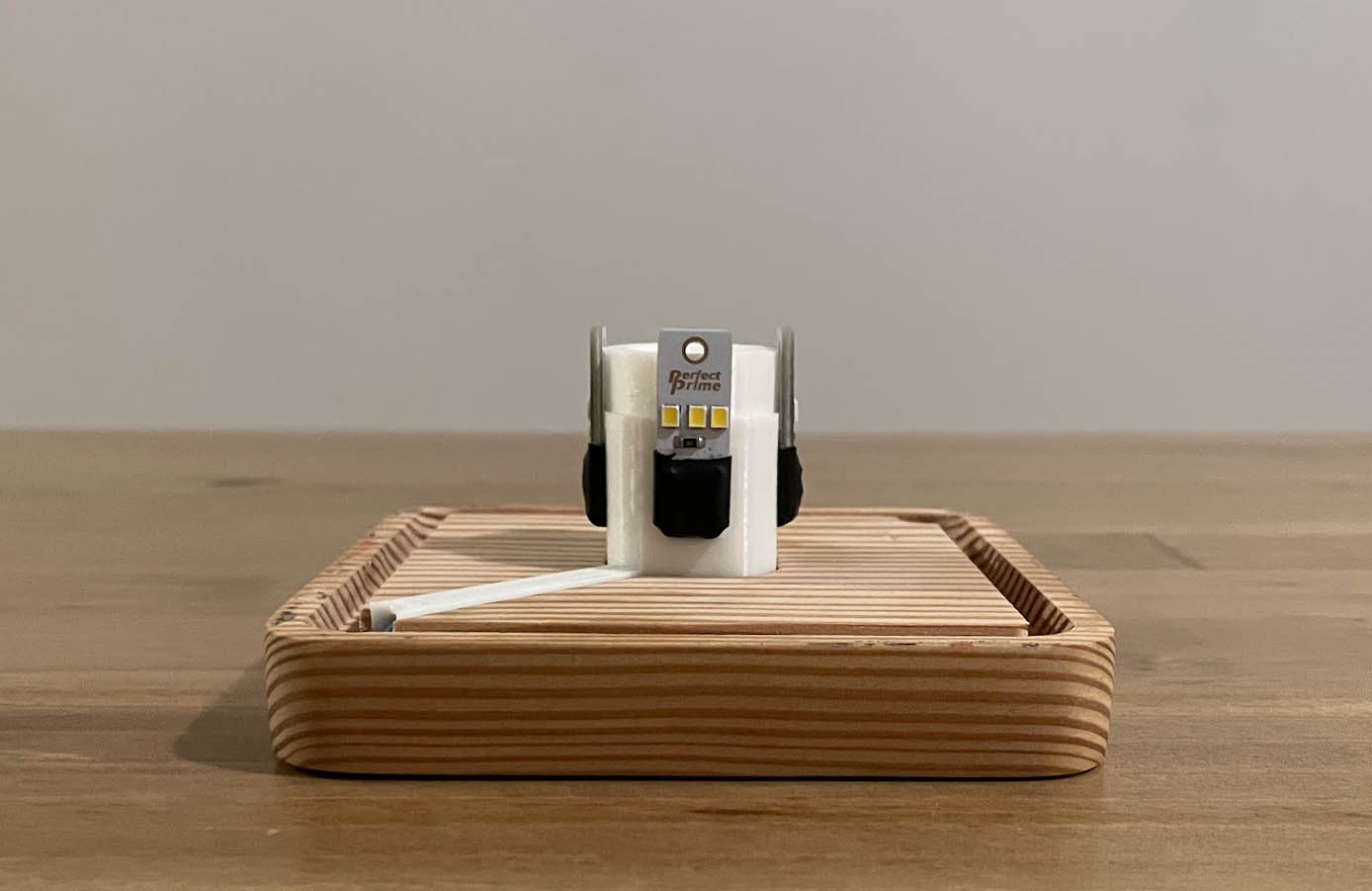
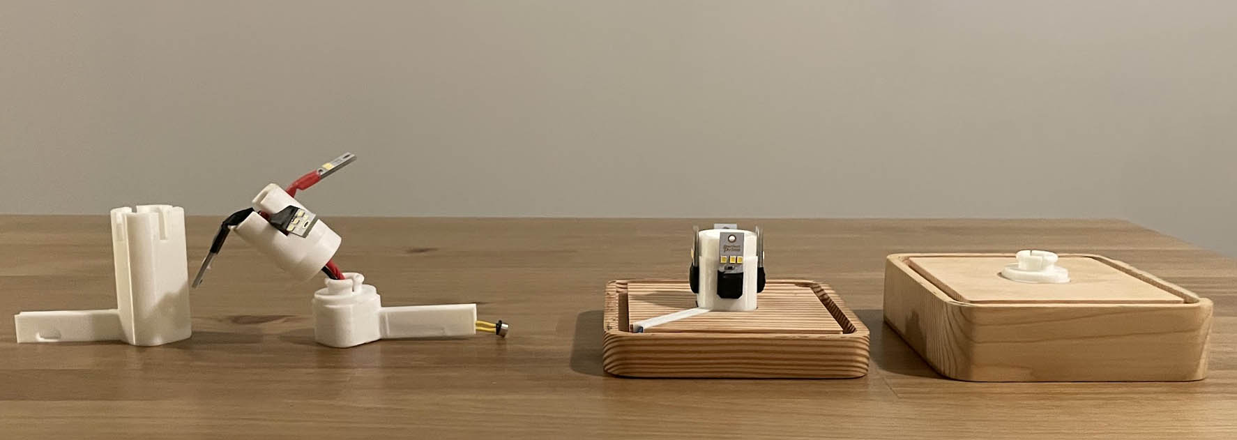 The internal electronics core assembly.
 Tolerance testing the friction fit of the internal chassis.
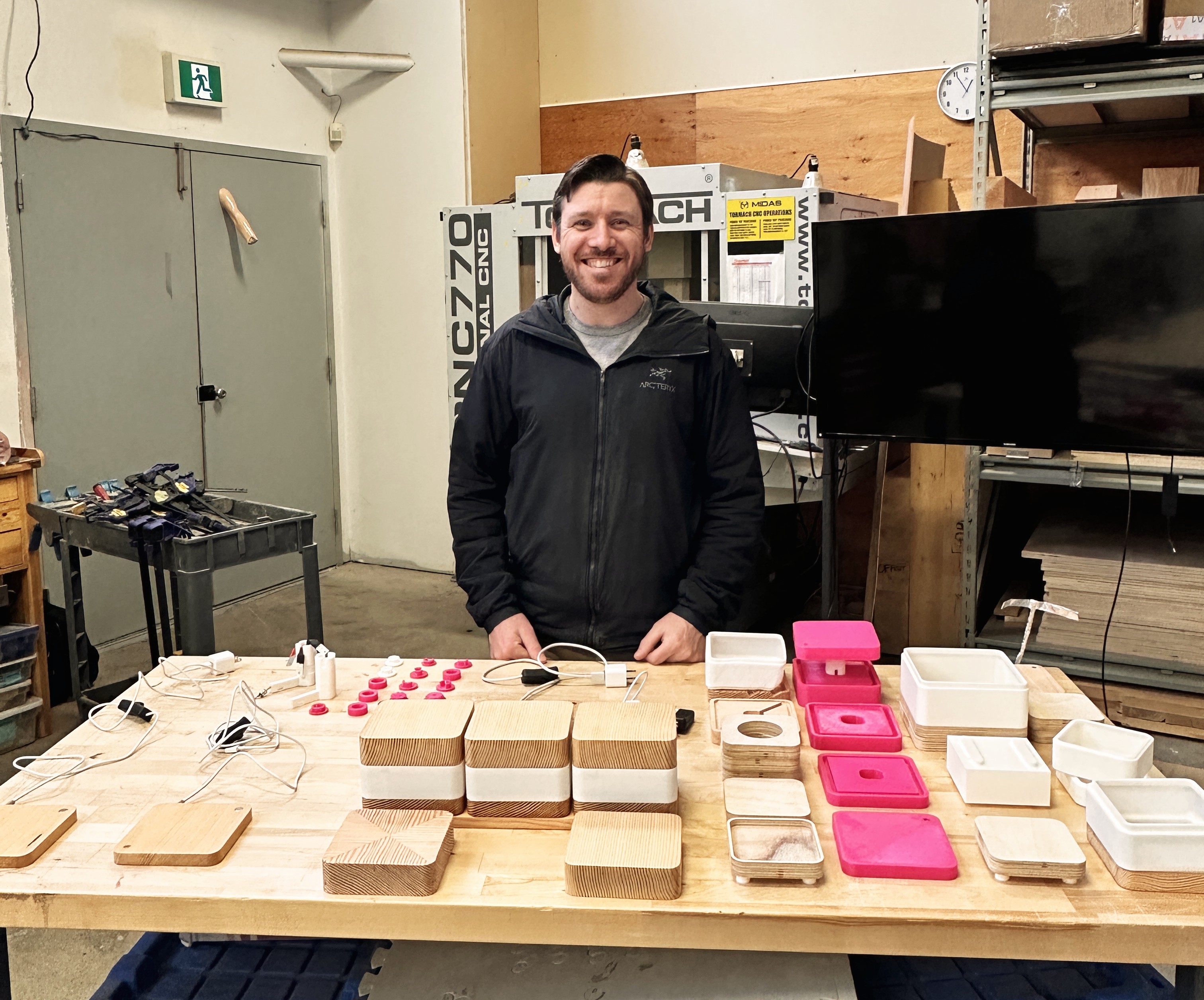
5. Manufacturing Process
Hybrid Fabrication Strategy
The aesthetic required the warmth of natural grain, but the mechanics required the precision of engineering plastics.
| Component | Manufacturing Method | Material |
|---|---|---|
| Housing | Subtractive (CNC Machining) | Solid Douglas Fir |
| Diffuser | Additive (SLA Printing) | Translucent Resin |
| Chassis | Additive (FDM Printing) | PETG / PLA+ |
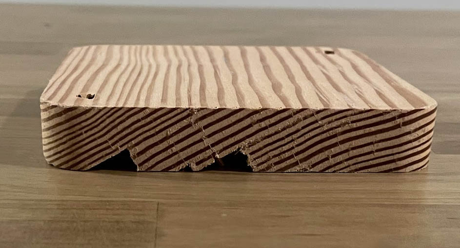
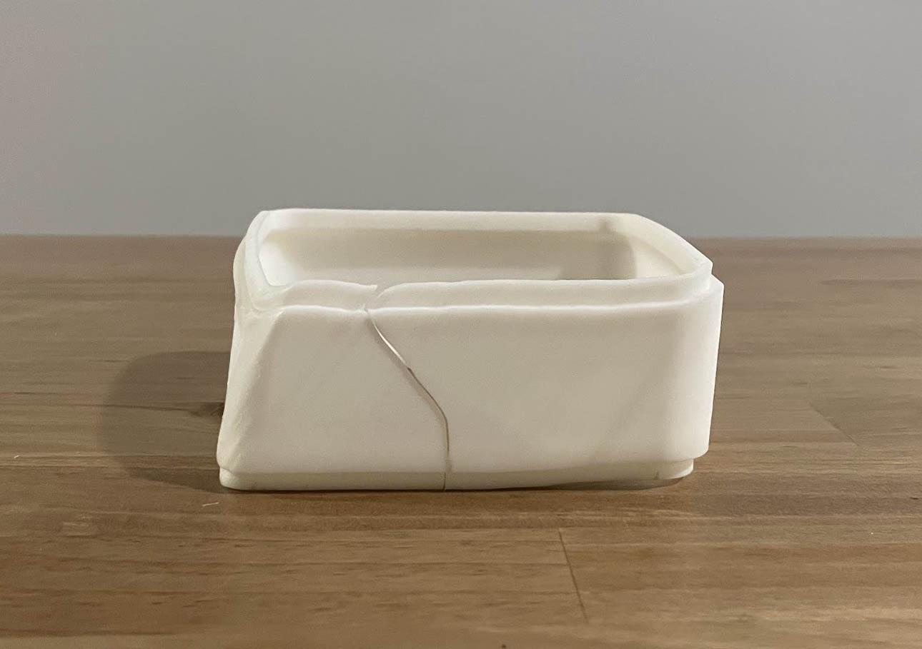
Failure Analysis & Process Control Early manufacturing attempts relied on double-sided machining (flipping the wood stock). This resulted in critical failures due to registration errors. I redesigned the part to utilize a Single-Setup Through-Bore to guarantee vertical concentricity.
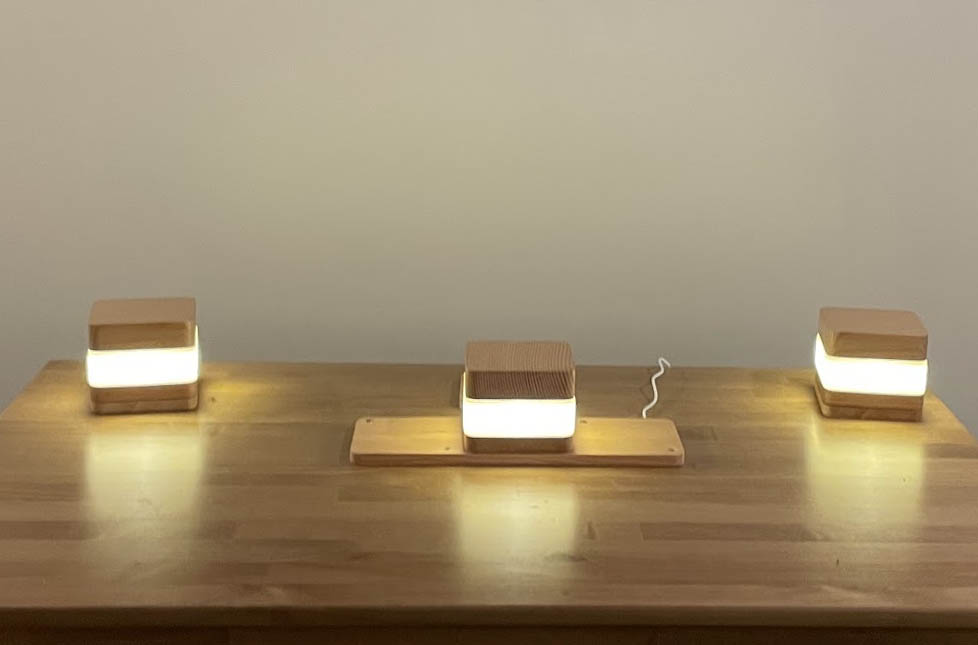
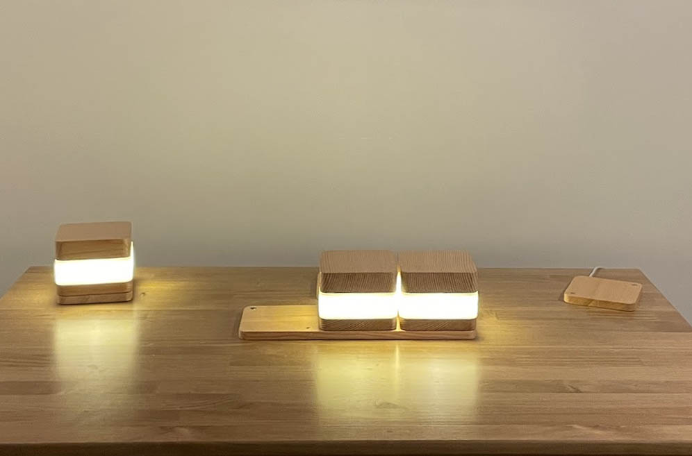
6. Project Gallery
The final result in context.
Tech Specs
- Material: Douglas Fir, SLA Resin, PLA
- Software: Fusion 360, Rhino
- Tools: 3-Axis CNC, Form 3L